
Titanic Images - The Shipbuilder - 4: Propelling Machinery
The combination of reciprocating engines with a Parsons low-pressure turbine, which has been adopted for the propelling machinery of the Olympic and Titanic, is one of the latest examples of progress in marine engineering.
The superior economy of the system is due to the fact that increased power is obtained with the same steam consumption by expanding the steam in the low-pressure turbine beyond the limits possible with the reciprocating engine.
Messrs. Harland & Wolff were among the first to see the advantages of the combination arrangement and to put the system to the test of actual experience.
This was done in the case of the Laurentic, already referred to, and the successful results obtained with this vessel led to the introduction of engines of the combination type in the new White Star liners and other vessels built and building at Belfast.
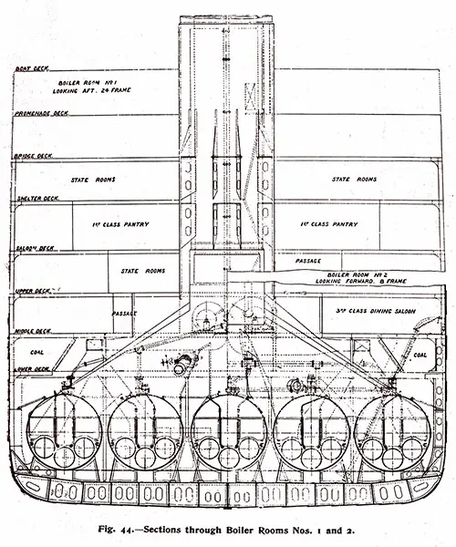
Fig. 44: Sections Through Boiler Rooms Nos. 1 and 2. The Shipbuilder (Midsummer 1911) p. 45. GGA Image ID # 10bcc0b520
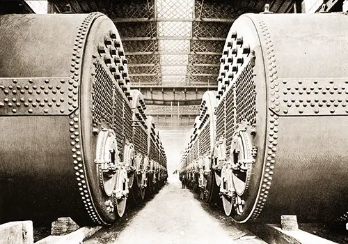
Fig. 45: Boilers Arranged in Messrs. Harland & Wolff's Works. To be Installed on the Olympic and Titanic. The Shipbuilder (Midsummer 1911) p. 46. GGA Image ID # 10bce2b411
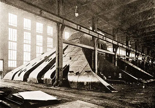
Fig. 46: Set of Boiler Uptakes. The Shipbuilder (Midsummer 1911) p. 47. GGA Image ID # 10bd3742b9
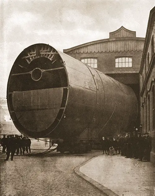
Fig. 47: Last Funnel of the Olympic Leaving the Shops. The Shipbuilder (Midsummer 1911) p. 48. GGA Image ID # 10bd401bf0
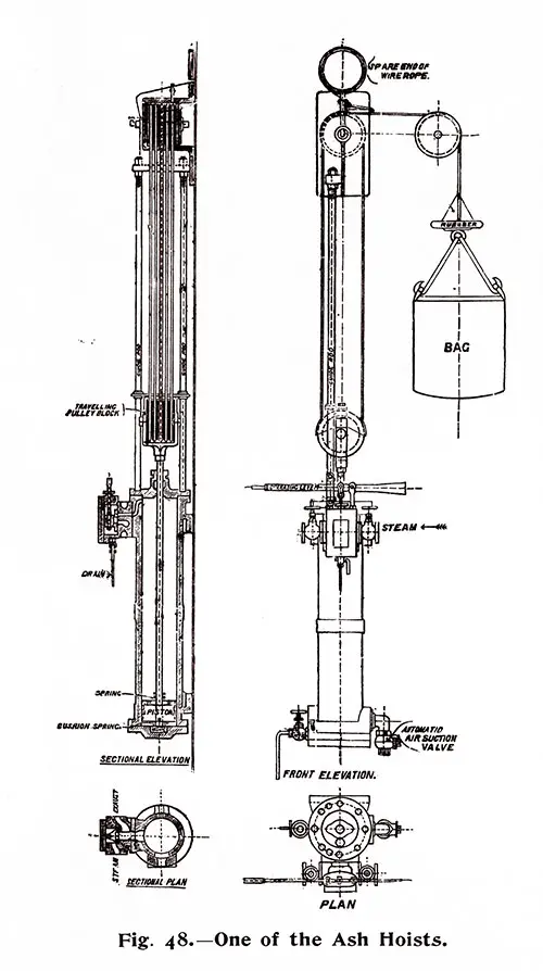
Fig. 49: One of the Ash Hoists. The Shipbuilder (Midsummer 1911) p. 49. GGA Image ID # 10bd8785ba

Fig. 49: Two of the Stokehold Fans. The Shipbuilder (Midsummer 1911) p. 49. GGA Image ID # 10bda7434f
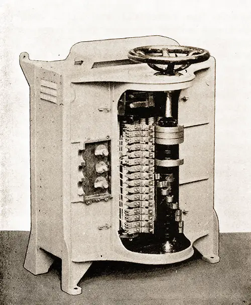
Fig. 50: Stokehold Fan Controller with Cover Removed. The Shipbuilder (Midsummer 1911) p. 50. GGA Image ID # 10bdbee363
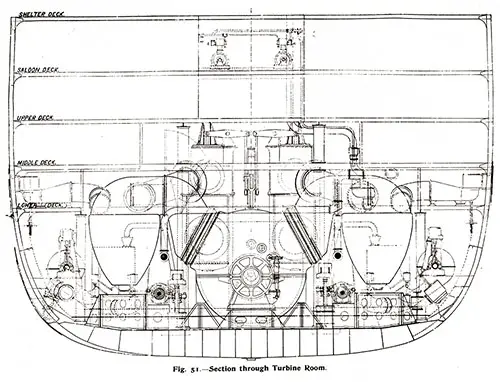
Fig. 51: Section Through Turbine Room. The Shipbuilder (Midsummer 1911) p. 51. GGA Image ID # 10bdc7b056
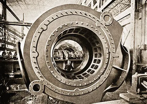
Fig. 52: Casing of one of the Change-Over Machines. The Shipbuilder (Midsummer 1911) p. 52. GGA Image ID # 10bdf2d0cb
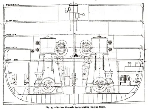
Fig. 53: Section Through Reciprocating Engine Rome. The Shipbuilder (Midsummer 1911) p. 53. GGA Image ID # 10be3c67d3
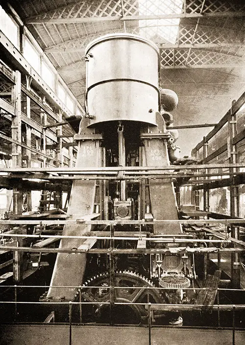
Fig. 54: One Set of Reciprocating Engines in the Erecting Shop. The Shipbuilder (Midsummer 1911) p. 54. GGA Image ID # 10be40741e

Fig. 55: Port Intermediate Cylinder. The Shipbuilder (Midsummer 1911) p. 55. GGA Image ID # 20c8251631
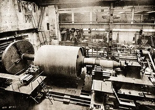
Fig. 56: Turbine Rotor in the Lathe. The Shipbuilder (Midsummer 1911) p. 56. GGA Image ID # 10beb8ea2f
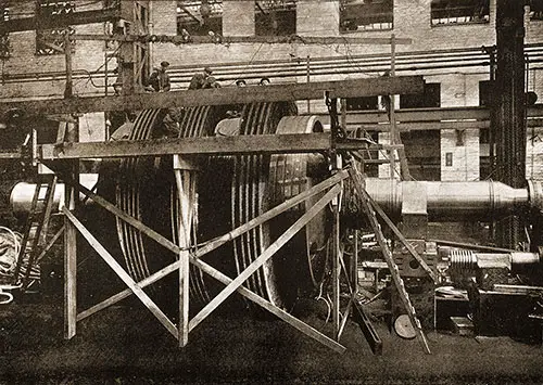
Fig. 57: Turbine Rotor in Process of Blading. The Shipbuilder (Midsummer 1911) p. 57. GGA Image ID # 10becefd14
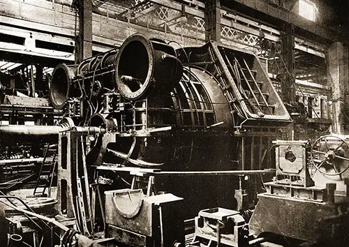
Fig. 58: Turbine Casing. The Shipbuilder (Midsummer 1911) p. 58. GGA Image ID # 10bf4daf90
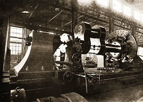
Fig. 59: Crank Shaft in the Lathe - For the Olympic. The Shipbuilder (Midsummer 1911) p. 59. GGA Image ID # 10bfcbbe35
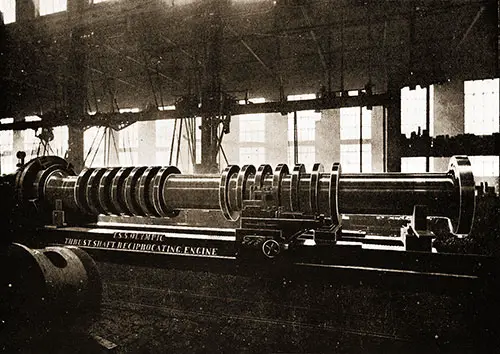
Fig. 60: One of the Thrust Shafts for the Olympic. The Shipbuilder (Midsummer 1911) p. 59. GGA Image ID # 10c03d3d80
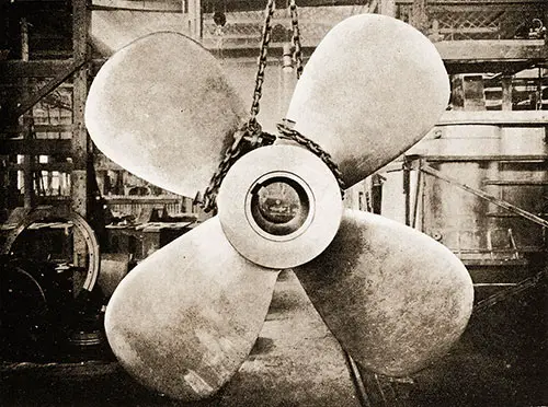
Fig. 61: The Center Propeller. The Shipbuilder (Midsummer 1911) p. 60. GGA Image ID # 10c0e13bee
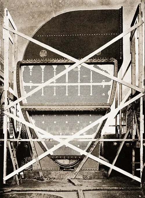
Fig. 62: One of the Main Condensers with Casing Partly Removed. The Shipbuilder (Midsummer 1911) p. 61. GGA Image ID # 10c1221fa5
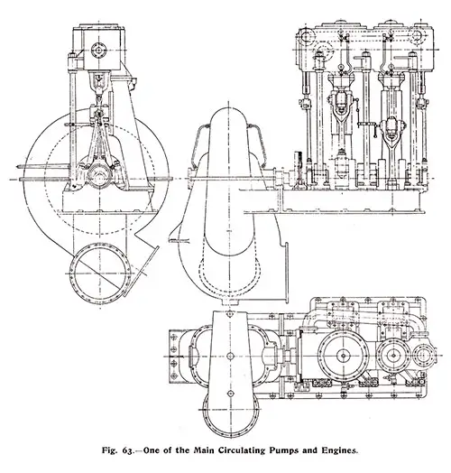
Fig. 63: One of the Main Circulating Pumps and Engines. The Shipbuilder (Midsummer 1911) p. 62. GGA Image ID # 10c1386887
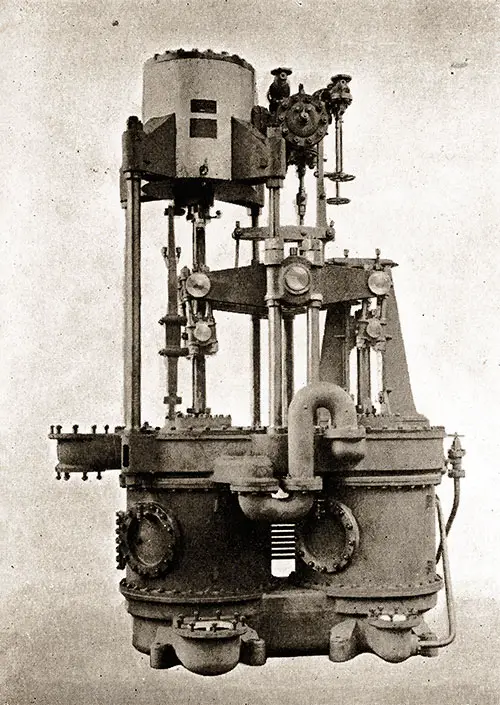
Fig. 64: One Set of Dual Twin Air Pumps. The Shipbuilder (Midsummer 1911) p. 63. GGA Image ID # 10c1448873
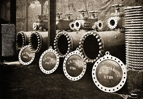
Fig. 65: Main Feed Filters of the Titanic. The Shipbuilder (Midsummer 1911) p. 64. GGA Image ID # 10c167ff32
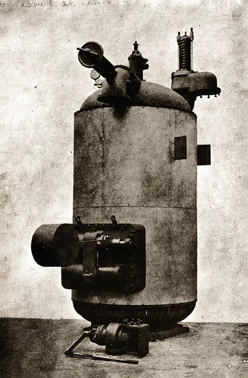
Fig. 66: Direct-Contact Heater. The Shipbuilder (Midsummer 1911) p. 65. GGA Image ID # 10c1ad77a0
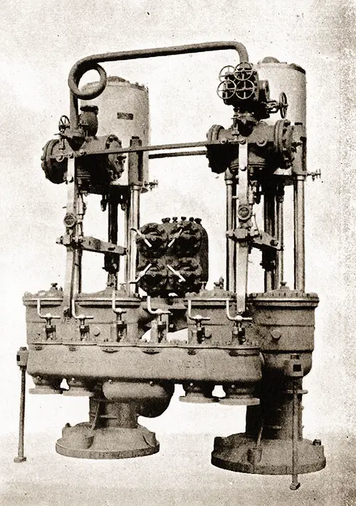
Fig. 67: One Pair of Vertical Direct-Acting Feed Pumps. The Shipbuilder (Midsummer 1911) p. 65. GGA Image ID # 10c1b523ff
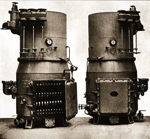
Fig. 68: Two of the Evaporators. The Shipbuilder (Midsummer 1911) p. 65. GGA Image ID # 10c2005cbe
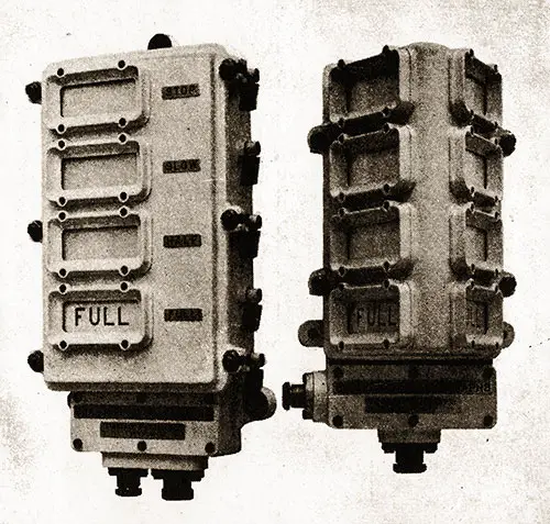
Fig. 69: Boiler Room Telegraph. Transmitter on the left, Receiver on the Right. The Shipbuilder (Midsummer 1911) p. 66. GGA Image ID # 10c2647026
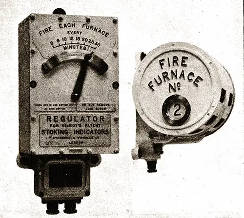
Fig. 70: Kilroy's Stoking Indicator. Regulator on the left, Indicator on the right. The Shipbuilder (Midsummer 1911) p. 66. GGA Image ID # 10c2e86ff9
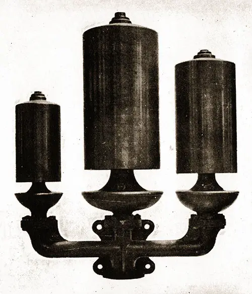
Fig. 71: One Set of Whistles - Used on the Olympic and Titanic. The Shipbuilder (Midsummer 1911) p. 66. GGA Image ID # 10c2f11540