
Titanic Images - The Electrician Magazine
The Electrician: The Oldest Weekly Illustrated Journal of Electrical Engineering, Industry, Science, and Finance and The Electrician Commercial and Industrial Supplement (Supplement to The Electrician).
Describes the various uses to which electricity is put on board the two latest White Star Liners, the Olympic and Titanic. These include, besides lighting, power for winches, cranes, fans, water-tight doors, and stoking and helm indicators. The cooling and heating equipment are also electrically worked, while a complete telephone and wireless installation are to be found on board. The differences between marine and land practice are noted.
Our image collection from The Electrician focuses on electric machinery, dials, instruments, lighting, and other related topics on the RMS Titanic.
Excello Lamp Lighting Sterage Deck of the "Olympic." Union Electric Co. has kindly furnished us with an illustration which shows an Excello lamp as used on board the new White Star liner “Olympic.” We understand that this photograph was taken during the trials of the liner, and that it shows an Excello lamp as used for the general illumination steerage deck. It is an extremely interesting example of electric lighting, and we hope that it will establish a precedent which will be regularly followed in the future. There should not be the least difficulty in an illumination problem of this kind. Supplement to The Electrician (23 June 1911) p. 71. GGA Image ID # 10f2ccfc07
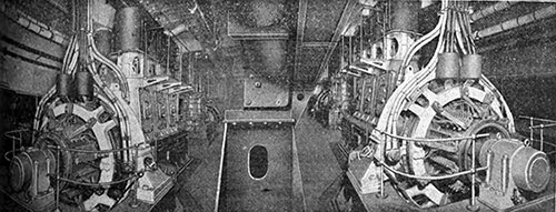
Fig. 1: General View of Generating Plant. The main generating plant, which is probably the largest electrical equipment that has been installed up to the present for marine work, consists of four 400 kw. Engines and dynamos, manufactured by Messrs. W. H. Allen, Son & Co., of Bedford, and having a collective output of 16,000 amps. at 100 volts, thus exceeding in current capacity many electrical central stations. The Electrician (28 July 1911) p. 615. GGA Image ID # 10f08c01b9
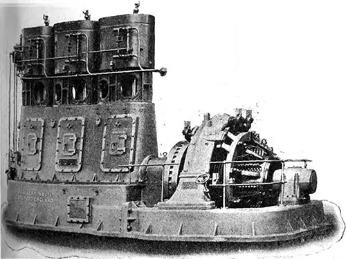
Fig. 3: One of the Main Generating Sets on the Olympic. The Electrician (28 July 1911) p. 617. GGA Image ID # 10f0a9c5e1
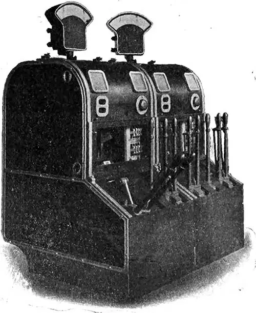
Fig. 4: Main Switchgear of Dynamo Nos. 1 and 2. Each set of main switchgear is operated by a row of five interlocked handle levers. The two outer handles are connected mechanically with the lighting and power equaling switches, respectively, and are interlocked so that they must be closed before the next handles, which operate the lighting and power main bus-bar selector switches, can be worked. The central handle is for closing and gripping the circuit breaker, and is also interlocked with the selector switch handles, so that the circuit breaker can only be closed and gripped when the selector switches are both in the "off" position. The Electrician (28 July 1911) p. 617. GGA Image ID # 10f0bde871
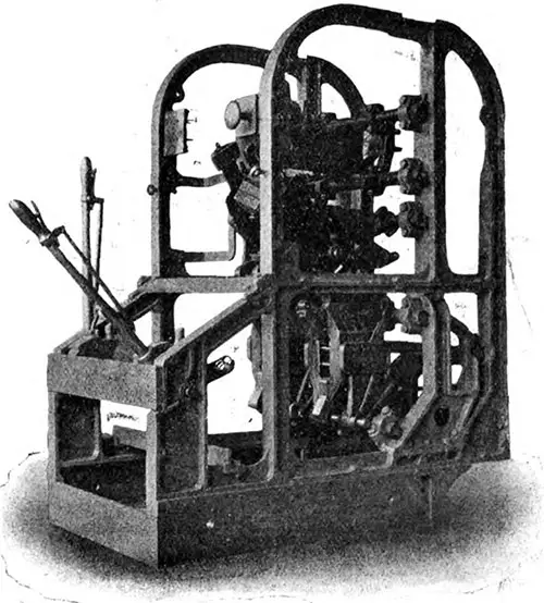
Fig. 5: View of a Main Generator Control Pillar During Construction, Showing the Circuit Breaker Above and the Two Selector Switches Below. The Electrician (28 July 1911) p. 618. GGA Image ID # 10f139dfdc
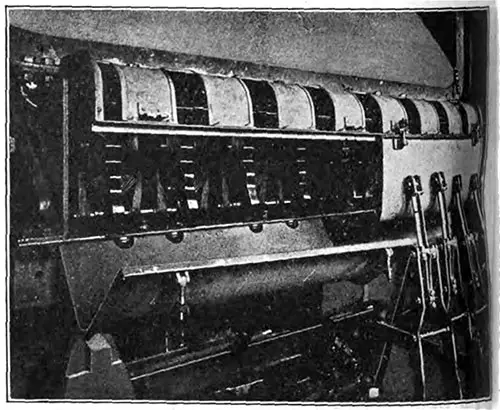
Fig. 6: Equalizing Switchgear. The enclosing case is arranged to open in two parts, the left-hand half being here shown open. The connecting links of some of the switches are shown on the right-hand side. The Electrician (28 July 1911) p. 618. GGA Image ID # 10f1962a40
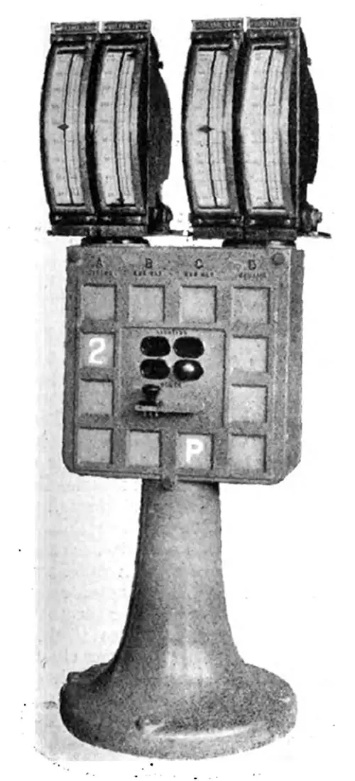
Fig. 7. Main Voltmeter Pillar. Voltmeters are used also for paralleling, are carried on a cast-iron pillar amidships between the main dynamo control gear. The voltmeters themselves are mounted in pairs; each pair being arranged so that they can swing round through 220 deg. The Electrician (28 July 1911) p. 619. GGA Image ID # 10f1978a72
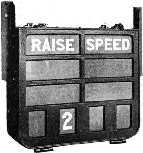
Fig. 8: Engine Room Signal from Switchboard. The signs, reading “start,” “raise speed,” “lower speed” and “stop,” combined with the number of the machine to which the signal applies, are visible in white letters on a red background when the lamps are illuminated by pressing a signal knob. The Electrician (28 July 1911) p. 619. GGA Image ID # 10f1d4d5b4
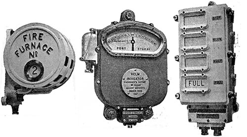
Fig. 9-11: Stoking Indicator; Helm Indicator; and Boiler Room Orders Telegraph. The Electrician (4 August 1911) p. 658. GGA Image ID #
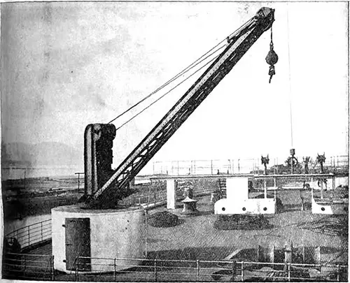
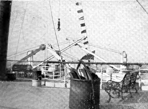
Fig. 12: 2 1/2 Ton Electric Crane. One of the little discomforts sometimes associated with modern ocean travelling is the noise caused by winches and other deck appliances, and although when on the high seas these are not much in evidence, yet when approaching port it is sometimes necessary to use them, as for instance when handling mails or passengers' luggage preparatory to dis embarkation. With a view to avoiding this on the “Olympic," the aid of electricity has again been invoked, with the result that all the winches in the vicinity of the passenger accommodation and the cargo cranes are electrically driven. The latter are made by Messrs. Stothert & Pitt, six having of 50 cwt. each, and two of 30 cwt. each. These cranes are fitted at the three after hatches and at the forward hatch near the passenger quarters. The Electrician (4 August 1911) p. 659. GGA Image ID #
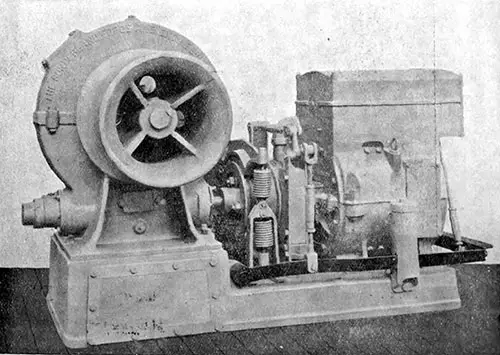
Fig. 13: 3-Ton Electric Cargo Winch. In addition to the electric cranes, there are four 3-ton electric cargo winches at the hatches, as well as four 15-cwt. electric boat winches made by the Sunderland Forge and Engineering Co. Ltd. The Electrician (4 August 1911) p. 659. GGA Image ID #
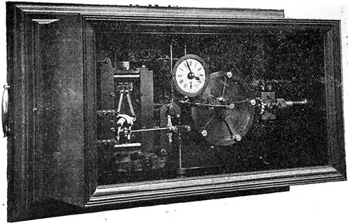
Fig. 14: Magneta Master Clock. The clocks, of which there are 48 throughout the vessel, are all actuated electrically, and worked in complete synchronism, so that each register exactly the same time; they are controlled by a master clock (Fig. 14) placed in the chart room under the control of the officers, who can set them backwards and forwards according to the longitude. The Electrician (4 August 1911) p. 660. GGA Image ID # 10f1e1da34
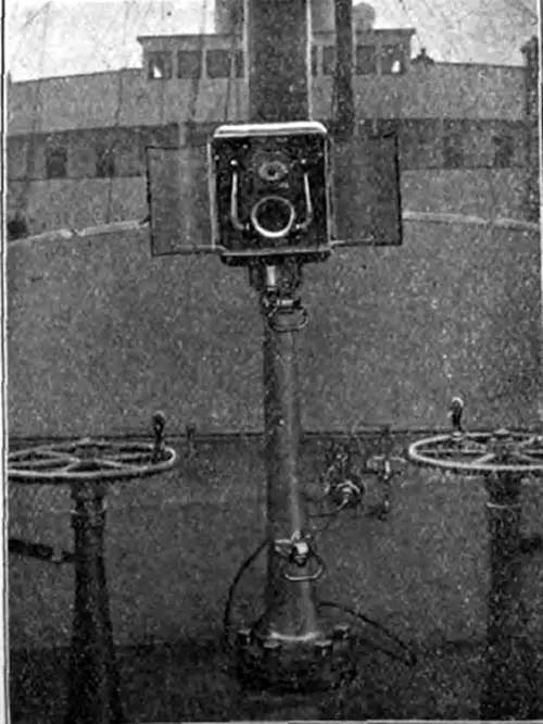
Fig. 15: Forecastle Telephone. The Electrician (4 August 1911) p. 660. GGA Image ID # 10f22d5c98
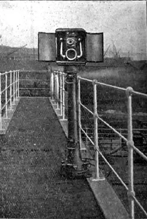
Fig. 16: Poop Telephone Instrument. The Electrician (4 August 1911) p. 660. GGA Image ID # 10f22f4ecd
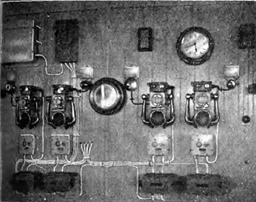
Fig 17: Wheelhouse Telephones. In the wheelhouse on the bridge (Fig. 17) four instruments are fitted, and each telephone is provided with an indicating device, and in addition to a flag showing, as is usual, a signal lamp is caused to glow upon a call being received. The Electrician (4 August 1911) p. 661. GGA Image ID # 10f25609d1
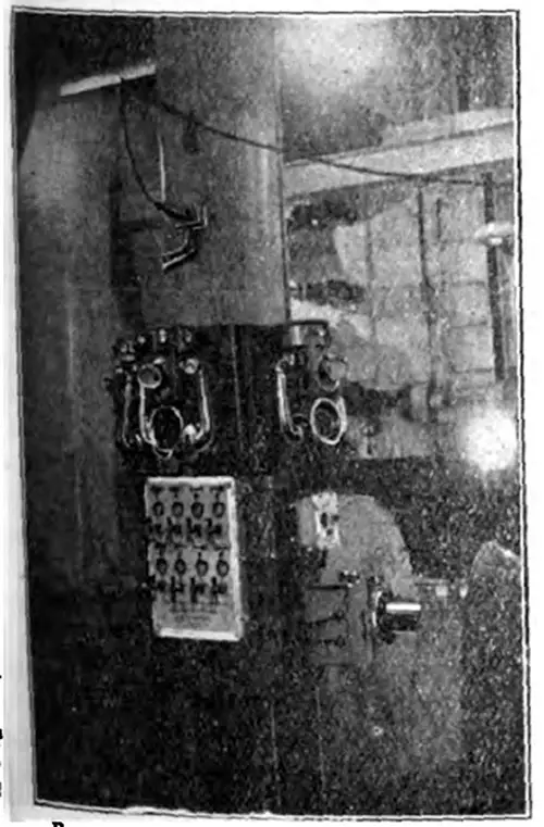
Fig. 18: Engine Room Telephones. In the engine room (Fig. 18) three telephones are employed, and the instrument for communicating with the boiler rooms operate in conjunction with a combined switch and indicator lighting both lamp and flag signals as previously referred to. In each boiler room, the telephone is mounted within a metal hood, and in addition a special calling receiver is provided at each station as well as a visual indicator. The Electrician (4 August 1911) p. 661. GGA Image ID # 10f270ccc8
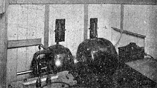
Fig. 19: Part of Marconi Transmitting Apparatus in Silence Cabin. The Electrician (4 August 1911) p. 661. GGA Image ID # 10f2a38382
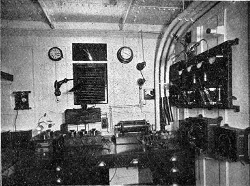
Fig. 20: Marconi Apparatus in Operating Cabin. No modern liner is complete without a wireless telegraph installation. With such an equipment not only is communication with ship or shore possible in case of accidents, but the passenger is enabled during the voyage to keep himself in touch with the world's news. The “wireless " apparatus on the “Olympic '' is of the Marconi type and consists of a 5 kw. motor-generator set combined with the latest type of valve receiver installed as a standby. The installation is designed to provide, when employed with a suitable aerial having a mean height of 170 ft., a working range of 250 nautical miles over water, and a maximum range considerably exceeding the above figure. The Electrician (4 August 1911) p. 661. GGA Image ID # 10f2cc2d4c